Modular 3D cabinets system
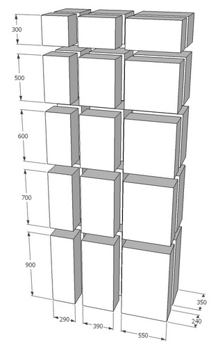
 Cabinets are designed as a set of 300, 500, 600, 700 and 900 mm height, 290, 390 and 550 mm width and 240 and 350 mm depth. Individual components are made of SMC material, which meets the V0 and HB40 flammability requirements with weatherproofing and suitable properties for electrotechnics.
 Individual cabinets can be arbitrarily assembled side by side or superimposed in cabinets or pillars of various depth. Individual sections are designed to be easy for assembling. Usage meets a wide range of electrical engineering requirements in individual sectors. 3D cabinets can be installed on a pole, wall-mounted, recessed and placed in the open space as a standalone pillar.
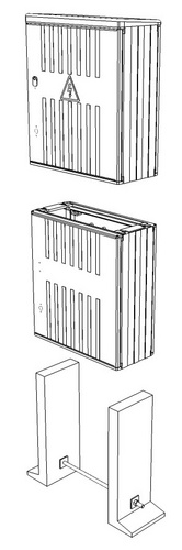
Cabinet door is fitted with ribs on the outer surface. That makes it difficult to put posters on it. Material and door construction eliminate distortion and material to bend. Door is sufficiently resistant to mechanical damage or destruction. Door opening is arranged at an angle of 200 °, what makes perfect access to the device in the switchgear for installer and eliminates door unintentional damage. Inner side of the door is prepared to incorporate auxiliary instrument holder and documentation casing. Door locking is possible using up to three-point leverage
lock system. Door dismantling is simple and can be done after opening the door by pressing catch spring and pin extension. The door assures cabinet ventilation without covering IP44 damage. Ventilation can be easily prevented by a foam (silicone) seal, thus can be achieved IP54. Cabinets design makes it possible to fit the door from both sides of the cabinet. Also to place the devices into the centre of the cabinet.
Sides of the cabinets are lightly fitted with ribs on the outer surface too. These ribs make difficult to pull the cabinet out from the masonry. The overall treatment of the sides secures individual cabinets side by side and superimposed in an endless series. The sides are moulded at two basic depths. Cabinet roof has one side angle of inclination. This solution allows to choose a side of slope and thus to drain the water forward or backward. Cabinets can be installed next to the wall and on the pillars next to the wall without water flowing down on the plaster.
Rear side of the cabinet, which is intended for installation of devices primarily, is supplied with moulded pal-nuts M6 or M8. It is also possible to make this part openable. The weight of the devices installed above cabinet must be taken into consideration. The cabinet door can be statically weighted with a maximum of 1.5 kg.
Assembly procedure for recessed cabinets
Cabinets are usually placed outside the building in recesses or loosely on pillars. There must be a space for operators in front of cabinet at least 800 mm depth. In case of installation near other distribution devices, safe distance must be kept. Fuse cabinets and switchboards are located according to the requirements of distributors.
Cabinet door is dismantled and the dimensions of the recess are checked before mounting. Plastic cabinets used in masonry are provided with perforations to prevent the cabinets to slip out of the wall.
Using the wooden wedges, cabinet is arranged to fit with the masonry surface. After recesses moisten, cabinet is fastened into it using the cement mortar (or the mounting foam). Cabinets sides should be set alongside with plaster, upper and lower parts should slightly protrude from the masonry. It is necessary to ensure size of cabinets before final masonry fixing, to avoid deformation (for example wooden spacer). Cabinet is then cleaned from the rest of cement mortar. It is good to disassemble the closing lath when connecting the power cables. The conductor ends and cables must be insulated, alternatively fitted with terminal crimp or terminal clamp. Conductors are shaped and earthing is connected to clamp (marked with an earthing mark). Cable entry must be sealed to prevent water getting into cabinets. This is ensured by thin layer of cement mortar or possibly walling the entire cabling space up. The ventilation of the cabinet is sufficiently ensured by an IP44 door labyrinth.
After cables assembly, closing bar is fitted and the wires are marked as necessary. Then the door is fitted and the door closing and locking is tested. Cabinet locks are made with a brass core and greased during production. Further greasing is no longer required.
Assembly procedure for pole mount cabinets
Pole mount cabinets are supplied with mounting stabilizers. There must be a space for operators in front of cabinet at least 800 mm depth. In case of installation near other distribution devices, safe distance must be kept. Disconnect cabinets are located according to the requirements of distributors.
Stabilizers for pole mounting are attached to the rear wall of the cabinets. The UP-370 stainless fastening strap or "BANDIMEX" system is used to fasten the cabinet to the pole.
Grommets for conductors’ entry/exit must be cut with a sharp device in the pre-pressed groove and chosen diameter (50, 63, 76 mm), before installing the protective power plastic pipes. Power plastic pipes bracket base (supplied separately as an accessory) is attached by the straps to the pole so that the top is approximately 0.5 m below the upper end of the pipes, and the lower to the centre between the cabinet and the upper bracket. For poles over 9 m in length, it is recommended to use three pieces of pipe brackets. The plastic pipes are fixed with a lower end on the grommets of the cabinet and attached to the base of the bracket by a divided part.
The door is removed from the cabinet and the conductors are pulled into the fixed pipes. The conductors are insulated and alternatively fitted with terminal crimp or "V" or "P" terminal clamps. Then the conductors are marked as needed. Before connecting to the grid, outlet pipes are fitted with covering (supplied separately as an accessory).
If the earthing outlet is fitted into the cabinet, it must also be protected by a plastic pipe. This pipe is attached to the pole in the same way as the outlet pipes for the conductors outgoing to overhead power line. The brass terminal M8 on the rear outer side of the cabinet is optionally connected to the housing ground. Cabinet earthing is connected to the outer rear part on the M8 brass bolt.
After that, the door is fitted and the door closing and locking is tested. Cabinet locks are made with a brass core and greased during production. Further greasing is no longer required.
Assembly procedure for wall-mounted cabinets
Wall-mounted cabinets are only those where cable entry can be secured. They are called as wall-mounted cabinets in the catalogue. There must be a space for operators in front of cabinet at least 800 mm depth. In case of installation near other distribution devices, safe distance must be kept. Cabinets are installed at least 0.6 m above the terrain.
Door and internal devices are removed from the cabinet and the mounting holes are drilled into the rear wall of the cabinet. The layout and number of holes must be adapted to the interior facilities of the cabinet and to the state and character of wall on which the cabinet is installed. For cabinet fastening common fasteners (plastic anchors, screws) are used. After fastening the cabinet to the wall, all devices are installed back.
Entry/exit conductors must be sufficiently protected from mechanical damage. When the conductors are plugged into the cabinet, they are insulated and alternatively fitted with terminal crimp or "V" or "P" terminal clamps. Then they are plugged in and the conductors are marked as needed.
All the coverings and cabinet door is mounted back and the door closing and locking is tested. Cabinet locks are made with a brass core and greased during production. Further greasing is no longer required.
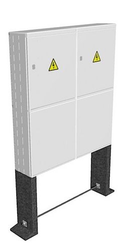
Mounting procedure for standalone pillar cabinets
 Standalone pillar cabinets are placed with the plinth as a pillar freely in the field or close to the buildings and fences. There must be a space for operators in front of cabinet at least 800 mm depth. Safe distance must be kept in case of installation near other distribution devices. The pillar consists of three basic parts: cabinet, the plinth and the base of the pillar. These parts can be ordered as a separate items. The plinth and the base of the pillar can be installed first in the open space and after finishing all the terrain adjustments, cabinet is mounted
and plugged in.
At first, plastic or concrete base of the pillar is assembled. Two base pieces are precisely, according to plinth width, spread out with the aid of provided bar brace, so that the pre-drilled holes (countersunk-head bolt) fit tightly in the plinth base holes. Then the base is assembled with a plinth. Set of the plinth and the base of the pillar are placed in the digged hole so that the plinth base is approximately 5 cm below the final terrain level. The plinth is put straight and ground is added on the sides if needed. If necessary (bearing capacity of the soil is reduced) plinth can be concreted. Then cabinet can be fastened to the plinth.
Cabinet cover is removed from the plinth by moving two stops toward the plinths axis and opening the cover forwards. Door is removed from the cabinet and then the cabinet is fastened to the plinth using provided fasteners. Then locking strips are demounted at the base of the plinth and at the bottom of the cabinet. Cable compartment is equipped with "L" console for cable attachment and to prevent cables from mechanical stress on the printed circuits too. The conductor ends and cables must be insulated, alternatively fitted with terminal crimp or terminal clamps. Conductors are shaped and connected to the clamps and marked as earthing (if the clamp is provided). Grounding conductor is connected there too.
When the cable mounting is completed, we continue with the pillar base covering. The base is covered step by step with inert material. After filling the entire base, locking laths are fixed and conductors are marked as necessary. Then the cover of the cable space and cabinet door are placed and the door closing and locking is tested. Cabinet locks are made with a brass core and greased during production. Further greasing is no longer required. Finally, the last terrain adjustments are made.