
3D System Pillar Installation on Uneven Ground: Special Cases
Always leave 800 mm of clear space in front of the enclosure, on level finished ground, so that the door can open by at least 90°.
Compact all backfill by hand to prevent the material from settling and leaving the equipment exposed, especially around the base of the pillar!
For example, you can add extra material to allow for expected settlement, then remove the excess or add more material as needed.
- Standard installation – level ground
- Standard installation – uneven ground
- Standard installation – slightly uneven ground (recessed base)
- Standard installation – uneven ground (with a plinth extension)
- Other installation options – uneven ground
- Additional measure to potentially reduce moisture
- Components used in special situations
1. Standard installation – level ground
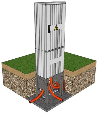
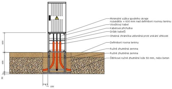
Standard installation on level ground.
2. Standard installation – uneven ground
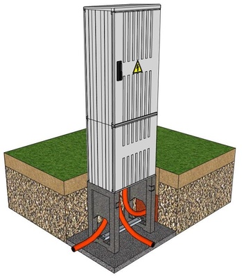
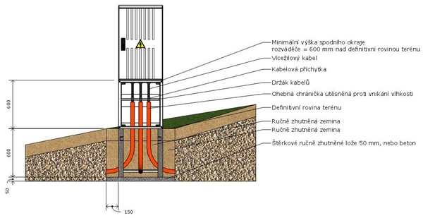
Standard installation on gently sloping ground. The surrounding area is then levelled to provide a flat area around the pillar. Levelling the ground around the pillar is also essential for the operator’s safety!
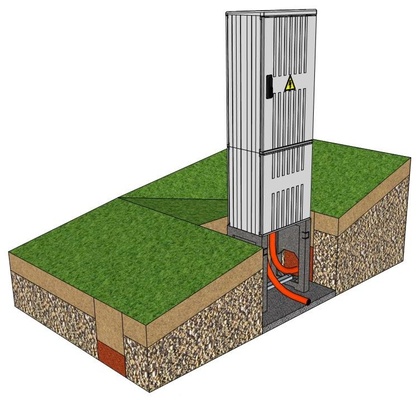
3. Standard installation – slightly uneven ground (recessed base)
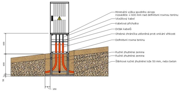
Standard installation on slightly sloping ground without subsequent landscaping. The cable compartment is recessed slightly into the ground to prevent unrestricted access to its lower section. Recessing the pillar foundation can be used in an open area where soil in front of the plinth cover can be dug away if access to the plinth is needed. Remove the soil in front of the plinth cover before accessing the plinth. The bottom edge of the enclosure may end up lower than the required 600 mm. Sloping ground in front of the pillar may create an unusual situation and could cause injury to the enclosure operator!
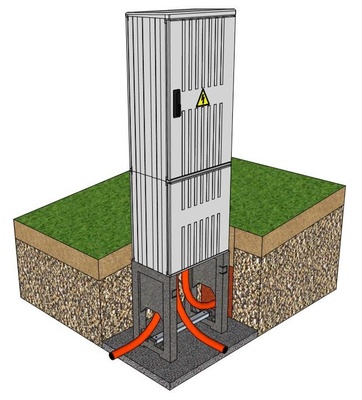
4. Standard installation – uneven ground (with a plinth extension)
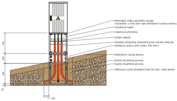
Standard installation on sloping ground without subsequent landscaping. A 300 mm high plinth extension raises the cable compartment and is recessed into the ground to prevent unrestricted access to its lower section. If access to the plinth is needed, simply remove the upper plinth cover. Sloping ground in front of the pillar may create an unusual situation and could cause injury to the enclosure operator!
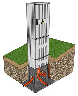
5. Other installation options – uneven ground
Another option for installing a pillar on sloping ground without subsequent landscaping is to fit the foundation with a CZK foundation front panel. It prevents unrestricted access to the lower part of the cable compartment. The CZK foundation front panel can be fitted to either the front or rear of the foundation, depending on the slope of the ground. The plinth cover remains accessible. The pillar trench may be shallower than the recommended frost-free depth of 600 mm. Sloping ground in front of the pillar may create an unusual situation and could cause injury to the enclosure operator!
The CZK foundation front panel and PSO plinth panel can be used together.
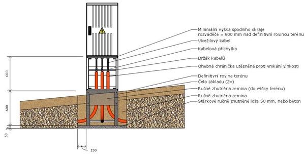
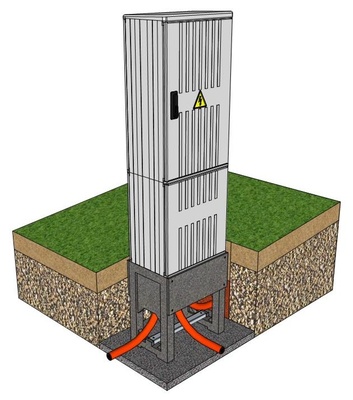
6. Additional measure to potentially reduce moisture
In areas with excessively damp soil, you can fit a PSO plinth panel and backfill the plinth with dry washed sand and expanded clay aggregate. This may reduce moisture inside the cabinet caused by rising damp from the soil, but it will not prevent condensation from moisture in the air. The illustration below shows how to use the PSO plinth panel as a potential moisture-reduction measure. We consider filling the plinth with additional material a supplementary measure for situations involving excessive moisture in the pillar plinth. It will not prevent water from condensing inside the enclosure. In unsuitable climatic conditions, where heat, moisture and frost alternate, the material inside the plinth may expand and cause damage.
The CZK foundation front panel and PSO plinth panel can be used together.
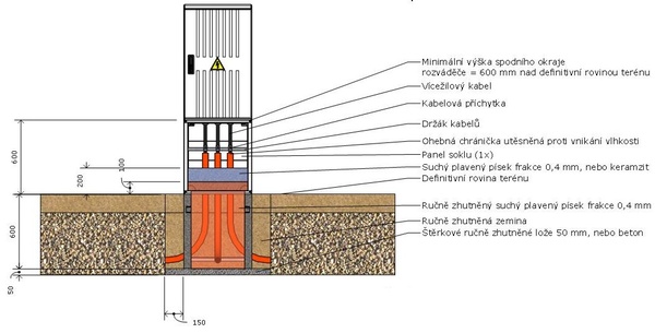
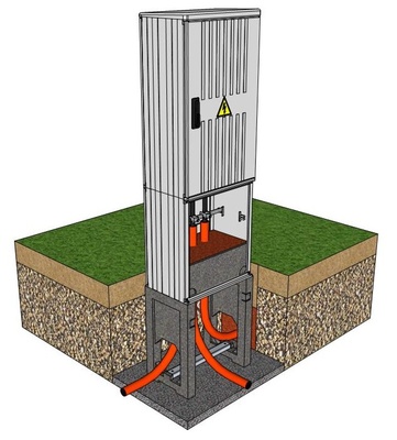
7. Components used in special situations
Installation methods 4, 5 and 6 use the pillar and 3D system foundation accessories described below.
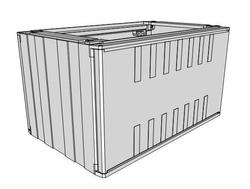 |
Plinth extension – a 300 mm high plinth. In general, 3D system plinths can be stacked if they have the same width and depth. For example, a type SO 1.2.3 plinth (300 mm high, 350 mm deep and 550 mm wide) can easily be fitted below a type SO 3.2.3 plinth (600 mm high, 350 mm deep and 550 mm wide). Similarly, a type SO 1.1.1 plinth (300 mm high, 240 mm deep and 290 mm wide) can be fitted below a type SO 3.1.1 plinth (600 mm high, 240 mm deep and 290 mm wide). See also: 4. Standard installation – uneven ground (with a plinth extension) |
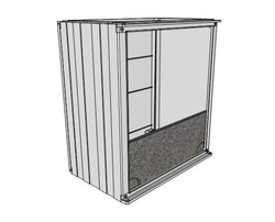 |
Plinth panel – a panel inserted into plinths 600 mm high (SO 3.X.X) or 900 mm high (SO 5.X.X), allowing material to be backfilled above ground level. For example, a type PSO X.X.3 panel can be used with a type SO 3.2.3 plinth (600 mm high, 350 mm deep and 550 mm wide). Similarly, one type PSO X.X.1 panel and one type PSO X.X.3 panel are used with an SO 3.1.13 plinth. We consider filling the plinth with additional material a supplementary measure for situations involving excessive moisture in the pillar plinth. It will not prevent water from condensing inside the enclosure. In unsuitable climatic conditions, where heat, moisture and frost alternate, the material inside the plinth may expand and cause damage. See also: 6. Additional measure to potentially reduce moisture |
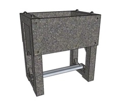 |
Foundation front panel – a panel that can be fixed to the front or rear of a pillar foundation as needed, covering the underground part of the pillar assembly. For example, one or two type CZK 0.X.33 panels can be used with a type ZK 0.2.33 foundation. Similarly, one or two type CZK 0.X.1 panels can be used with a type ZK 0.1.1 foundation. We consider fitting foundation front panels a supplementary solution for pillars in unsuitable locations or where the surrounding ground has not been properly prepared. This solution does not remove the need to level the ground for the operator’s safety. |