AHVO cabinets system

 Cabinets are designed as a monoblock. That means that the individual cabinet is moulded at one time without any other components required for assembly. Cabinets have a basic height 585 mm, a depth 216 mm and a width of 420 mm. The cabinets are made of SMC thermosetting material, which meets the requirements for flammability V0 and HB40 with weatherproofing and are suitable properties for electrotechnics.
Individual components are designed to be simple to assemble and use to meet a wide range of industry-specific electrotechnical requirements. The AHVO® cabinets can be mounted on a pole, wall-mounted, recessed and placed as a standalone pillar.
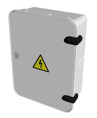 Cabinets’ doors are smooth on the surface, what does not interfere aesthetics of the cabinet. Material and door construction eliminate any buckling or bending. Door can be opened at an angle of 200 °. This prevent door against possible damage during work inside the cabinet. Door is sufficiently resistant to mechanical damage or destruction. Door locking is possible with a single lock or one leverage lock. Door removal is simple and can be done by opening the cabinet. It is possible to install the cabinet ventilation lath without damaging the IP44 coverage.
General processing of the cabinet assures the assembly of individual superimposed cabinets in the theoretically endless line.
Cabinets are designed with respect to the acquisition costs and all technical requirements. In case of cabinets and especially pillars, number of mouldings is reduced, what means lower price of AHVO® cabinets.
Rear wall of the cabinet, which is intended primarily for devices installation, is provided with a slat for auxiliary segments installation. The slat contains pressed-in M6 or M8 nuts.
Assembly procedure for recessed cabinets
 Cabinets are usually placed outside the buildings, or into the wall recesses or as a standalone pillar. There must be a space for operators in front of cabinet at least 800 mm depth. In case of installation near other distribution devices, safe distance must be kept. Fuse boxes and switchboards are installed according to distribution company requirements.
Door is set down before installation and the recesses dimension is checked.
Using wooden wedges, the cabinet is straightened in such a way that the cabinet protrudes from the masonry with a raised frame. After the recess has been moistened with water, cabinet is consolidated with cement mortar (or with mounting foam). It is necessary to assure the cabinet dimensions (e.g. wedge it) before the final fixing to avoid cabinet deformation. The cabinet is then cleaned from the cement mortar residues. During supply cables connecting it is recommended to dismount the closing slat (connecting cabinets only) by turning and pulling the locking pins.
The conductor ends and cables must be insulated, alternatively fitted with terminal crimps or “V” terminal clamps. Conductors are shaped and earthing is connected to clamp (marked with an earthing mark). The cable entry must be sealed to prevent water getting into cabinets. This is ensured by thin layer of cement mortar or possibly walling the entire cabling space up. The ventilation of an IP44 door labyrinth can be improved by air slat (see accessories section).
After the cables assembly, the closing bar is fitted and the wires are marked as necessary. Then the door is fitted and the door closing and locking is tested. Cabinet locks are made with a brass core and greased during production. Further greasing is no longer required.
Assembly procedure for pole mount cabinets
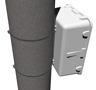 Pole mount cabinets are produced for pole mounting and are fully prepared for it. There must be a space for operators in front of cabinet at least 800 mm depth. In case of installation near other distribution devices, safe distance must be kept. Disconnect cabinets are located according to the requirements of distributors.
Stabilizers for pole mounting are attached to the rear wall of the cabinets. The "BANDIMEX" system is used to fasten the cabinet to the pole.
Grommets for conductor entry/exit must be cut with a sharp device in the pre-pressed groove (and chosen diameter (50, 63, 76 mm)) before installing the protective power plastic pipes. Power plastic pipes bracket base (supplied separately as an accessory) is attached by straps to the pole so that top is approximately 0.5 m below the upper end of the pipes, and the lower to the centre between the cabinet and the upper bracket. For poles over 9 m in length, it is recommended to use three pieces of pipe brackets. The plastic pipes are fixed with a lower end on the grommets of the cabinet and attached to the base of the bracket by a divided part.
Door is removed from the cabinet and the conductors are pulled into the fixed pipes. The conductors are insulated and alternatively fitted with terminal crimp or "V" or "P" terminal clamps. Then the conductors are marked as needed. Before connecting to the grid, outlet pipes are fitted with covering (supplied separately as accessory).
If earthing outlet is fitted into the cabinet, it must be also protected by a plastic pipe. This pipe is attached to the pole in the same way as the outlet pipes for the conductors outgoing to overhead power line. The brass terminal M8 on the rear outer side of the cabinet is optionally connected to the housing ground (in case that cabinet is equipped with it). Cabinet earthing is connected to the outer rear part on the M8 brass bolt.
The door is fitted and the door closing and locking is tested. Cabinet locks are made with a brass core and greased during production. Further greasing is no longer required.
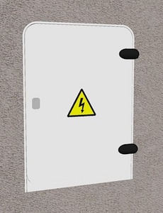
Assembly procedure for wall-mounted cabinets
Wall-mounted cabinets are only those where the cables entry can be secured. They are called as wall-mounted cabinets in the catalogue. There must be a space for operators in front of cabinet at least 800 mm depth. In case of installation near other distribution devices, safe distance must be kept. Cabinets are installed at least 0.6 m above the terrain.
Door and internal devices are removed from the cabinet and the mounting holes are drilled into the rear wall of the cabinet. The layout and number of holes must be adapted to the interior facilities of the cabinet and to the state and character of the wall on which the cabinet is installed. For cabinet fastening common fasteners (plastic anchors, screws) are used. After fastening the cabinet to the wall, devices are mounted back.
Entry/exit conductors must be sufficiently protected from mechanical damage. When the conductors are plugged into the cabinet, they are insulated and alternatively fitted with terminal crimp or "V" or "P" terminal clamps. Then they are plugged in and the conductors are marked as needed.
All the coverings and cabinet door are mounted back and the door closing and locking is tested. Cabinet locks are made with a brass core and greased during production. Further greasing is no longer required.
Mounting procedure for standalone pillar cabinets
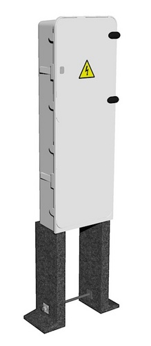 Standalone pillar cabinets are placed freely in the field or close to the buildings and fences. There must be a space for operators in front of cabinet at least 800 mm depth. In case of installation near other distribution devices, safe distance must be kept. The pillar consists of three basic parts: cabinet, plinth and base of the pillar. These parts can be ordered as separate items. The plinth and the base of the pillar can be installed first in the open space and after finishing all the terrain adjustments, cabinet is mounted and plugged in.
At first plastic or concrete base of the pillar is assembled. Two base pieces are precisely, according to plinth width, spread out with the aid of provided bar brace, so that the pre-drilled holes (countersunk-head bolt) fit tightly in the plinth base holes. Then the base is assembled with a plinth. Set of the plinth and base of the pillar are placed in the digged hole so that plinth base is approximately 5 cm below the final terrain level. The plinth is put straight and ground is added on the sides if needed. If necessary (bearing capacity of the soil is reduced) plinth can be concreted. Cabinet can be fastened to the plinth then.
Door is removed from the cabinet. Furthermore, the cabinet cover is removed from the cabinet by turning and pulling the locking pins and pulling the cover forward. Then the closure slat at the bottom of the base is removed by turning and pulling the locking pins. The cable compartment is equipped with "L" console for cable attachment and also to prevent cables from mechanical stress on the printed circuits. The conductor ends and cables must be insulated, alternatively fitted with terminal crimp or terminal clamps. Conductors are shaped and connected to the protective-conductor terminal and marked as earthing (if the clamp is provided with the cabinet). Grounding conductor is connected there too.
When the cable mounting is completed, we continue with pillar base covering. We cover the base step by step with inert material. After filling the entire base, the locking lath is fixed and conductors are marked as necessary. Then the cover of the cable space and cabinet door are placed and the door closing and locking is tested. Cabinet locks are made with a brass core and greased during production. Further greasing is no longer required. Finally, the last terrain adjustments are made.