
Enclosure Marking According to PNE 35 7040
A guide to understanding the enclosure identification code defined by PNE 35 7040.
The PNE 35 7040 coding system standardises enclosure identification across manufacturers using a single code. However, it does not cover every configuration and option available for our enclosures, so we use PNE 35 7040 only as a secondary identification system.
Please note: Our range does not include enclosures with any code other than xxxx/Nxxxx. The letter “N” identifies the thermoset material SMC, which we use exclusively to manufacture our enclosures.
When searching, use only the part of the code before the slash (for example, SR402), or replace any character after the slash with “N” (SR402/NVW4 instead of SR402/PVW4).
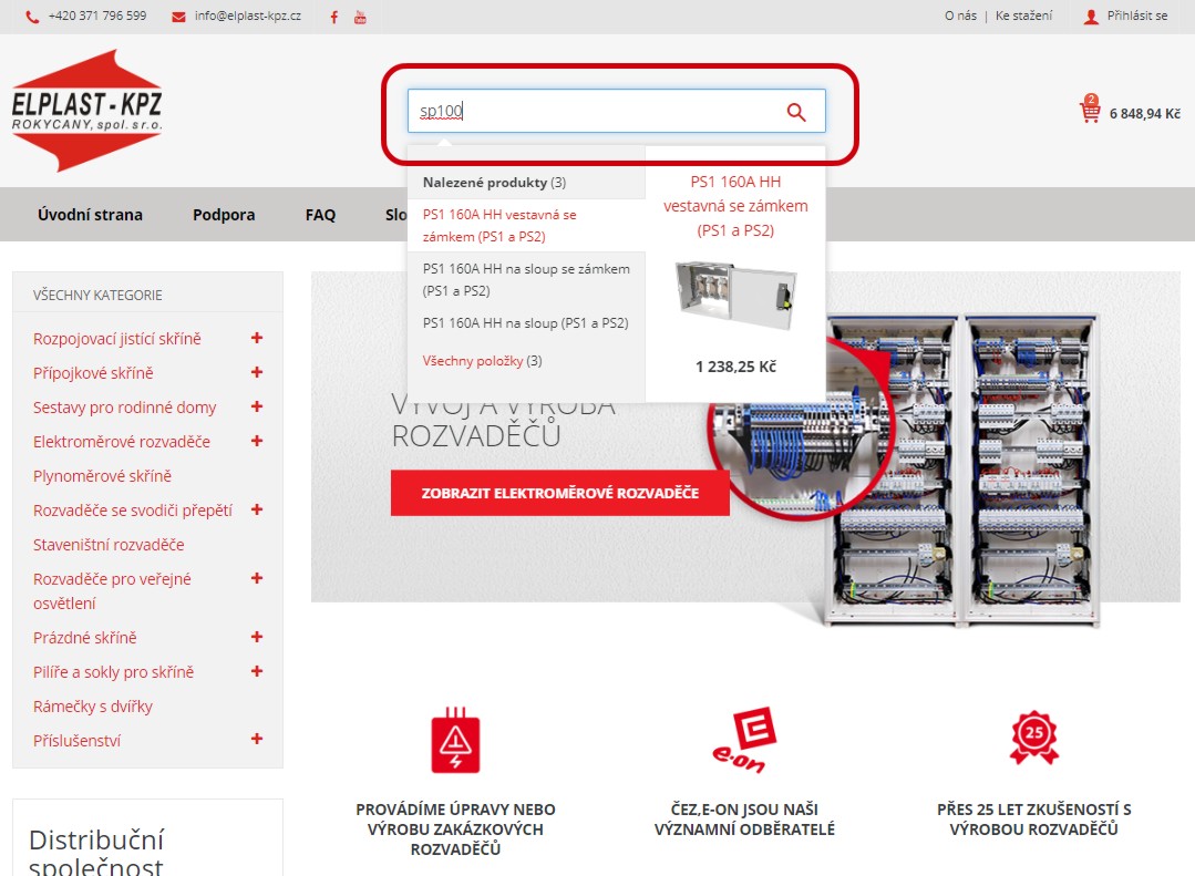
You can search our catalogue by the PNE 35 7040 code using the “Search” box at the top of the page.
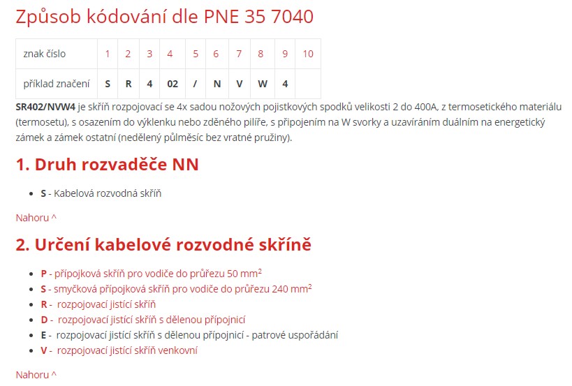
Coding system according to PNE 35 7040
| Character position | 1 | 2 | 3 | 4 | 5 | 6 | 7 | 8 | 9 | 10 |
| Example code | S | R | 4 | 02 | / | N | V | W | 4 |
SR402/NVW4 is a sectionalising cabinet with four sets of size 2 knife fuse bases rated up to 400 A, made from thermoset material, for installation in a recess or brick pillar, with W-type terminals and dual locking for an energy-industry seal and a standard lock (undivided half-moon type, without a return spring).
1. Type of low-voltage switchboard
- S – cable distribution cabinet
2. Purpose of the cable distribution cabinet
- P – service connection cabinet for conductors up to 50 mm2
- S – loop-in service connection cabinet for conductors up to 240 mm2
- R – sectionalising and protective cabinet
- D – sectionalising and protective cabinet with a split busbar
- E – sectionalising and protective cabinet with a split busbar, arranged in tiers
- V – outdoor sectionalising and protective cabinet
3. Number of protective device sets
- 1 –
- 2 –
- 3 –
- 4 –
- 5 –
- 6 –
- 7 –
- 8 –
- 9 –
- 0 – ten or more
4. Fuse base used
- 27 – E25 fuse bases
- 33 – E33 fuse bases
- 00 – size 00 knife fuse bases
- 01 – size 1 knife fuse bases
- 02 – size 2 knife fuse bases
- 07 – combination of size 00 and size 1 fuse bases
- 08 – combination of size 00 and size 2 fuse bases
- 09 – combination of size 1 and size 2 fuse bases
- 10 – horizontal fuse switch-disconnector, size 00 or 000
- 11 – horizontal fuse switch-disconnector, size 1
- 12 – horizontal fuse switch-disconnector, size 2
- 20 – size 0 fuse rails
- 21 – size 1 fuse rails
- 22 – size 2 fuse rails
- 30 – vertical fuse switch-disconnector, size 00
- 31 – vertical fuse switch-disconnector, size 1
- 32 – vertical fuse switch-disconnector, size 2
- 41 to 49 – fuse rail combinations, 22+ (1×20 to 9×20)
- 51 to 59 – fuse switch-disconnector combinations, 32+ (1×30 to 9×30)
- 60 – combination of size 00 fuse rails and switch-disconnectors
- 61 – combination of size 1 fuse rails and switch-disconnectors
- 62 – combination of size 2 fuse rails and switch-disconnectors
- 71 – SPV 10 cylindrical fuse bases
- 72 – SPV 14 cylindrical fuse bases
- 73 – SPV 22 cylindrical fuse bases
- 81 – OPV 10 cylindrical fuse switch-disconnectors
- 82 – OPV 14 cylindrical fuse switch-disconnectors
- 83 – OPV 22 cylindrical fuse switch-disconnectors
- 99 – combination of fuse bases agreed with the manufacturer
5. Slash
The fifth character is always a slash.
6. Material
- P – all-plastic thermoplastic construction (not supplied by us)
- N – all-plastic thermoset construction
- B – concrete frame with sheet-steel door (not supplied by us)
- K – concrete frame with plastic door (not supplied by us)
- O – sheet-steel construction
7. Cabinet construction and mounting type
- V – for installation in a wall recess (or brick pillar) with a reaction-to-fire class other than A1
- F – for installation in a wall recess with a different reaction-to-fire class than A1
- P – for installation on a freestanding pillar (plinth)
- S – for attachment to an overhead-line support
- N – for wall mounting with a reaction-to-fire class other than A1
- E – for wall mounting with a different reaction-to-fire class than A1
- K – compact complete assembly (cabinet, pillar and foundation part)
- U – universal (except K)
- C – assembly consisting of a cabinet and plinth, without a foundation part
8. Cable/conductor connection code
- S – flat screw terminal with washer for cable lugs
- M – flat screw terminal with a captive nut for cable lugs
- P – direct conductor connection to a structural terminal
- V – V-shaped size 00 fuse-base flag for a clamp (the flag and clamp form the fuse-base V terminal)
- W – V-shaped size 1 or 2 fuse-base flag for a clamp (the flag and clamp form the fuse-base V terminal)
- C – auxiliary V-shaped transition terminal for end or loop-in connection to size 00 fuse bases using clamps
- D – auxiliary V-shaped transition terminal for end or loop-in connection to size 1 or 2 fuse bases using clamps
- E – auxiliary V-shaped transition terminal for loop-in connection to size 00 fuse bases using a single clamp
- F – auxiliary V-shaped transition terminal for loop-in connection to size 1 or 2 fuse bases using a single clamp
9. Door locking code
- 1 – single utility lock for the energy sector according to ČSN 35 9754, Annex 1
- 2 – three-point locking with a utility lock for the energy sector according to ČSN 35 9754, Annex 1
- 3 – sealable M6 screw
- 4 – dual locking (energy-sector lock according to ČSN 35 9754, Annex 1, plus a lock for other sectors according to Annex 2)
- 5 – three-point locking for a cylinder lock
- 6 – single-point locking for a cylinder lock
- 9 – special locking as specified by the customer
10. Variable character
a. Number of unfused incoming connections in sectionalising cabinets
- 1 –
- 2 –
b. Outgoing conductor connection method for service connection cabinets
- S – flat screw terminal with washer for cable lugs
- M – flat screw terminal with a captive nut for cable lugs
- P – direct conductor connection to a structural terminal
- V – V-shaped size 00 fuse-base flag for a clamp (the flag and clamp form the fuse-base V terminal)
- W – V-shaped size 1 or 2 fuse-base flag for a clamp (the flag and clamp form the fuse-base V terminal)
c. Number of unpopulated protective device sets
- (1) –
- (2) –
- (3) –
- (4) –